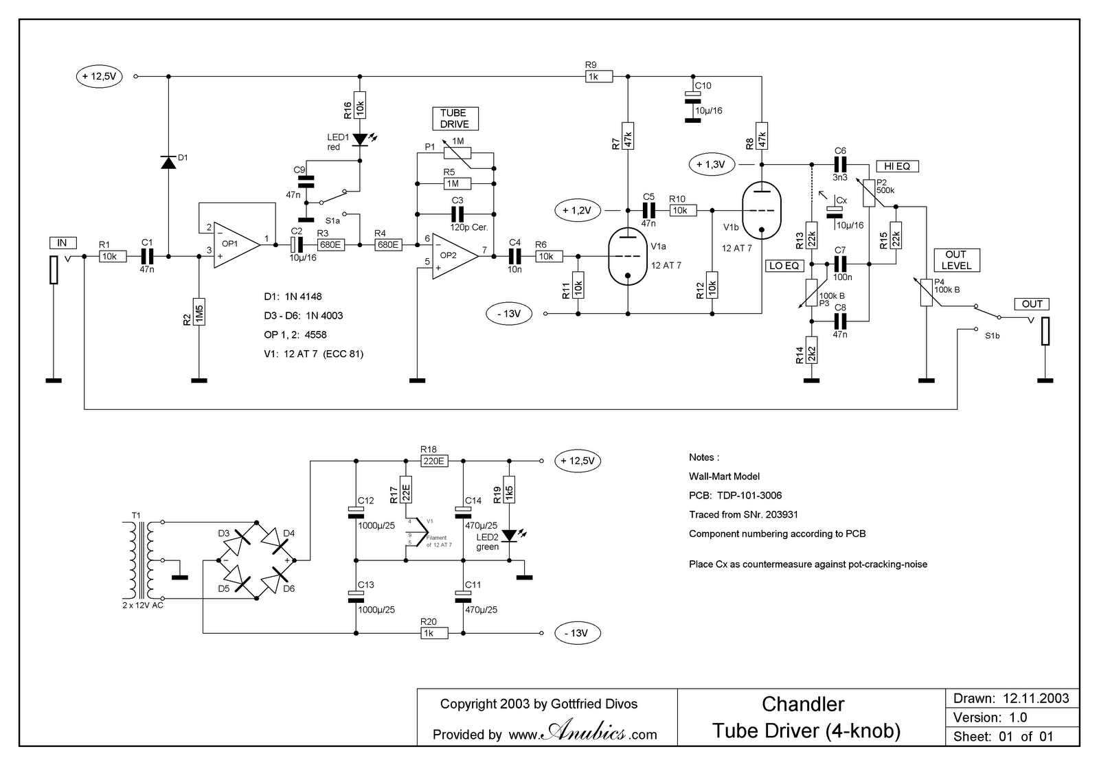
The cure for his is larger diameter ports to slow the air speed down but then they need to be longer to maintain the correct tuning frequency. Power compression where the voice coil heats up and turns the increased power into heat. Wall flexing which produces all sorts of unwanted nodes and cancellations. The cabinet design is often a limiting factor, commercial builders usually build down to a price not up to a spec. You can add more power and a better speaker and it will probably sound a bit louder but "boxy" as hell. I have done it on a better designed cab than that and it wasn't really a success. I swapped the speaker for a more sensitive one (db/W measured 1 metre from the cone) which also handled about double the power. Yes it was loud but not in a good way.Īdding a steep sloped high pass filter that cuts frequencies that are only sapping power (below the speaker/cab lower 3db point that are neither audible nor useful). Somewhere between 35 and 80Hz is usual dependant upon the cab design and speaker. It also protects the speaker from frequencies below the resonant frequency where the speaker "unloads" and flaps about wildly without having the resistance offered by the cab to restrain it.ĭrNomis wrote:I noticed that according to the schematic for my TKO 80 amp, the power amp section is a Quasi-Complementary type, and I was wondering how hard would it be to mod it to a Complementary type, it does have a +V and -V supply rail so it shouldn't be too hard, should it?. I would look for a more efficient speaker. You are not going to get much more volume out of it. I guess small bear didn't sell dust caps for the pots 3 years ago - you can see the double sided tape keeping the pots from shorting out the board.Not much in actual volume for the most part.another idea is. The pots were all scratchy and exact replacements are not obtainable so I managed to fit 16mm long pin Alphas in there. I tacked a 10uF capacitor on the end of R13 as suggested in the analogguru schematic to keep DC of the LO EQ pot.

In the Baja design, the filaments are powered via AC connected via a 10 ohm / 1 Watt resistor - switched to that design (maybe unnecessarily), which is why R17 is removed and the 10 ohm resistor spans from one pad of D3 to one pad of R17, there is jumper from the D4 pad to the non CT AC lead to connect that resistor to power. I removed D3 and D4 and connect the AC power to CT and the junction of D5 and D6. My original schematic matches this - but the wall wart CT transformer is hard to find so I converted to non CT wall wart.


 0 kommentar(er)
